Top rated

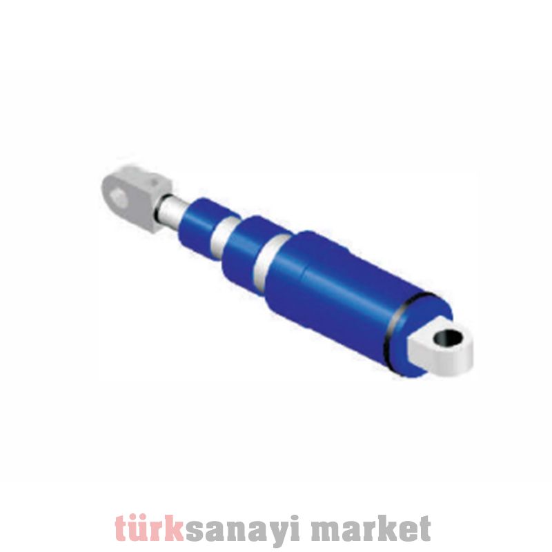
STAGED CYLINDER
Hydraulic power transmission systems can be examined in two basic structures according to their working principles. These are,
· Hydrodynamic power transmission systems
· Hydrostatic power transmission systems
1.1. HYDRODYNAMIC POWER TRANSMISSION SYSTEMS
In hydrodynamic drive, equipment with non-positive displacement is used. The basic working principle of these equipment is to increase the energy levels by accelerating liquid (or gas) media with the help of their wings.
(Here, v: Speed of the habitual medium, ω: Rotation speed of the wings, m: Mass of the accelerated fluid medium.)
There are two ways to increase the energy levels of non-positive equipment (valid for the pressure level), these are;
a-Increasing the amount of accelerated (transmitted) mass by enlarging the wings.
b-Increasing the speed of the fluid.
In order to increase the speed of the fluid, stepped wing structures are used (Figure 3).
Increasing the pressure levels that can be used with such mechanisms therefore leads to expensive solutions. For this reason, in systems operating on the hydrodynamic principle, pressure is generally used up to 250 bar. In general, such systems are preferred for low pressure but high flow applications. In addition, since the kinetic energy in the liquid cannot be transmitted without loss over long distances, the pump and turbine are placed very close to each other in this drive style.
The equipment used in rare mechanisms where this drive style is used for power transmission are known in the industry as hydraulic clutches and torque converters. (Figure 4)
Torque converters and hydraulic clutches are used in automobiles, agricultural vehicles and many power transmission systems. (Figure 5)
1.2. HYDROSTATIC POWER TRANSMISSION SYSTEMS
In hydrostatic drive, the hydraulic fluid sucked from a tank by a positive displacement pump is transmitted to the hydromotor and cylinders by the transmission and control elements. These elements are used by converting hydraulic energy into mechanical energy. (Figure 6)
Hydraulic power transmission finds application areas in the industry in two basic structures. These are;
· Industrial hydraulic applications (Figure 7): Such applications are mostly seen in power transmission systems of fixed hydraulic machines such as machine tools, apparatus, etc.
· Mobile hydraulic applications (Figure 8): Mobile hydraulic applications are seen in mobile machines such as work machines and cranes. The structure of the power unit and hydraulic valves in such systems is different from industrial hydraulic applications.
Differences between industrial hydraulic applications and mobile hydraulic applications;
· In industrial hydraulic applications, space constraints are less common in the assembly of the system on the machines. Therefore, power units can be made larger in such designs.
Valves used in industrial hydraulics are not directly connected to each other, connections are made by means of metal wedges to form valve islands. These wedges must contain many channels in complex circuits. Therefore, it is important that their designs are made carefully. Valve blocks can be directly connected to each other in mobile hydraulic applications. Working pressures are usually selected lower in industrial hydraulic applications.
However, the equipment used in both industrial hydraulic applications and mobile hydraulic applications are similar to each other in terms of their physical structures and operating methods.
2.ELEMENTS USED IN HYDROSTATIC DRIVE
2.1.PUMPS
Hydraulic pumps convert mechanical power into hydraulic power. The general structure of a pump used in hydrostatic drive is shown in Figure 9.
Positive displacement pumps are used in hydrostatic drive. These pumps suck the oil under the effect of atmospheric pressure in the hydraulic tank thanks to the vacuum they create in the increasing volume regions. Then, the oil is pushed into the circuit thanks to the decreasing volume region formed in its internal structure while the shaft continues to rotate (Figure 10).
Text Box:
Here, the displacement of the pump is the amount of oil it can theoretically press in one rotation.
Vg= πd2L/4 (cm2/4)
The pumps that meet the high pressure requirements in hydraulic power transmission systems in the most economical way are the positive displacement type. A positive displacement pump produces pressure as much as the resistance it encounters, and the pressure level of the hydraulic fluid it presses can change continuously in proportion to the resistance it encounters in the system. If the pump outlet is completely closed, very high pressures may occur in the system, which may cause damage, depending on the torque of the drive motor.
There are various types of pumps according to their designs.
-Classification of pumps according to the variability of their internal volumes,
a-Fixed displacement pumps; The internal volumes of these pumps cannot be changed, the amount of hydraulic pressure they put into the system is proportional to their rotation speed.


