Top rated

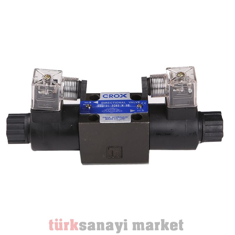
Hydraulic Valve
Hydraulic Valves, In hydraulic systems, the energy transmission between the pump and the user is provided by connections and lines arranged in accordance with the purpose.
Hydraulic Valves In order to obtain the quantities expected from the users such as power, rotational moment, speed or revolution number and direction of movement and to maintain such things in accordance with the given operating conditions, valves are placed in the lines as energy control elements. These hydraulic valves provide the testing or adjustment of pressure and volumetric flow. Each valve creates a resistance to the fluid passing through.
Directional test valves are used to test the flow of fluid in hydraulic lines and to change or start or stop the direction of movement of hydraulic cylinders and motors. Directional control valves can be operated manually or automatically.
Automatic mechanical movement can be controlled by electrical signals, hydraulic valves by power or compressed air.
Although there are many types of directional control hydraulic valves, all of these are made of the same simple basic elements or a combination of elements.
Direction control valves are classified in many different ways.
1. Functions of Valves • Hydraulic Valve Opens and closes the path of the fluid. • Changes the direction of the fluid. • Sends the fluid to the tank. • Adjusts the operating speed of the receivers by controlling the flow rate of the fluid. • Protects the circuit elements against high pressures. Sends the fluid with increasing pressure to the tank. • Controls the pressure of the fluid and ensures that the circuit elements operate at certain pressures. • Controls the pressure, flow rate and direction of the fluid at certain time intervals. • Some valves can perform one or more of the tasks listed above. 2. Hydraulic Valve Pressure test Valves are valves used in the pressure lines of hydraulic systems, ensuring that the pressure of the fluid is at the desired value.
Types According to Where They Are Used; 2.1. Pressure safety valves Allows the pressure to be sufficient to overcome the resistance that occurs for the work to be done, and sets a limit on the pressure (=end of stroke) that may occur on it. Types of Hydraulic Valves and Working Methods Hydraulic Valves are period elements that determine the direction in which the hydraulic fluid will go, change its direction when desired, and control the pressure and flow rate of the fluid. 19 2.2. Pressure reducing valves In hydraulic circuits, it may be necessary to use more than one user element (cylinder, hydromotor) to be operated at different pressures and the user elements may also need to operate at different pressures. In such cases, pressure reducing valves are used. Normally in the open position. When the pressure increases, it switches to the closed position. There are different types as two-way and three-way. 2.3. Pressure sequence valves Pressure sequence valves are used to operate more than one number of user elements in a hydraulic circuit, such as cylinders and motors, at different times and pressures. The working principle is similar to pressure safety valves.
Normally in the closed position. It opens at the desired pressure and activates the other user elements. 2.4. Discharge valves are used to send hydraulic fluid to the hydraulic tank. Normally closed, the valve opens when a warning is received and sends the fluid to the tank. 3. Hydraulic Valve Directional test Valves These are the valves that determine when and which path the fluid should follow in hydraulic circuits. They change the flow path when desired; they open and close the flow path when desired. Control VALVES General publication Single frame shows the flow or pressure test. (It can be in many different types depending on the operating conditions, pressure and flow shape)
Two squares show that the test valve has two positions Three squares show that the control valve has three positions It is one of the easy representations of the control valve on the diagram. 3 A,B = user lines P = Pump connection T = Tank connection 4/3 directional valve 4 Connection 3 Position 20 ASSOCIATION OF CONSTRUCTION MACHINERY ENGINEERS 3.1. Schematic representation of directional control valves • Each position of the valve should be shown with a square. • The flow directions of the fluid are indicated with arrows.
• Closed paths are determined with a horizontal line. • Valve connections are indicated with short lines. • Marking of valve positions; valve positions are marked with letters from left to right. In three-position valves, the center position is indicated with 0, you can see the slide structure inside the direction control valve in the picture below. 3.2. Schematic vision of direction test valves 3.3. Direction test valve control types 3.4. Lettering of valve connections; • P=Pressure line A,B,C….=Working line or working line • R,S,T=Reservoir (return) line • X,Y,Z=Pilot (warning) line • L=Leakage line 3.5. Definition of direction control valves; • 2 / 2 = Way number/position number • When 3 /2 valve definition is made, it is understood that the valve is 3-way, 2-position. 3.6. Normal positions of the valves: • Valves in hydraulic circuit drawings


